The simple song:
It is organised as building blocks,
combined according to personal taste
and need,
best if organised on a pre-drilled universal printed circuit
board,
with holes for the input, output sockets, potentiometers,
all
drilled into pcb,
then screwed and fixed with bolts,
with
holes-conforming alu frontplate drilled in parallel,
and later pushed over
it,
which would even act as Faraday cage,
besides being nice &
shinny;
solution for the bottom?
-> I leave totally to your aesthetic
touch,
but the mixer will be 'elegantly' slim,
because we'll use an
outside universal power plug.
This is what Monika wanted
And here is
a 'physical' layout consisting of:
-> one microphone preamp,
-> one (passive) stereo line input,
-> one channel output
amplifier,
-> stabilizer circuit
... and its elements follow (with certain variations):
but before the nice drawings download there is time for a brief 'basics'
course!
and now the nice drawings must have downloaded!
 all input signal grounds should go directly to stabilizer one-point
ground, (however - they can be first connected connected all together)
all input signal grounds should go directly to stabilizer one-point
ground, (however - they can be first connected connected all together)
the alu
frontplate should be connected only once to ground -> at a microphone input
(the most sensitive one),
capacitor at the input should be 1microfarad
plastic foil, resistor 100Kohm going from the input socket to ground is to
prevent a 'thump' when connecting an input cable;
there is a
possibility for a 'phantom' microphone supply - the red resistor; attention:
there are electret microphones which have an additional ring -> like
the stereo mini jacks - these get their 'phantom' power at the ring (get a
stereo input socket!) - connect the red resistor on the ring;
the trimmer may
serve for setting the input sensitivity but it can be also eliminated - together
with the associated 10 microfarad electrolitic capacitor.
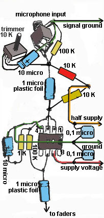
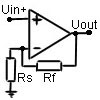
Micro preamp is
the simplest operational amplifier non-inverting design, therefore a good op-amp
is needed (TL 071, NE 5534, CA 3140); the design is for single voltage supply
(and op-amps are not), therefore half_the_supply voltage line is needed
everywhere.
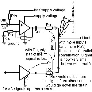
also: very close
to every op-amp a couple of 'blocking' capacitors (0,1microfarad 50V ceramic)
are needed (to block the noise from the two voltage supply lines).
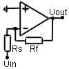
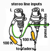
For stereo (or mono) line inputs no op-amp is used, just resistor from
the input socket to the ground and capacitor from the input socket to the next
(mixing, prelistening, send) stage;
however, adding a 'buffer' stage
(-> a mic preamp with feedback resistor replaced by a wire) can make things
easier with send potentiometers (-> cheaper and smaller!). Double op-amps can
be used (also 8 pins/ same price! -> NE 5532, TL 072,...).
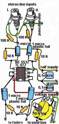
this is how a
buffer (with double op-amp) looks like:
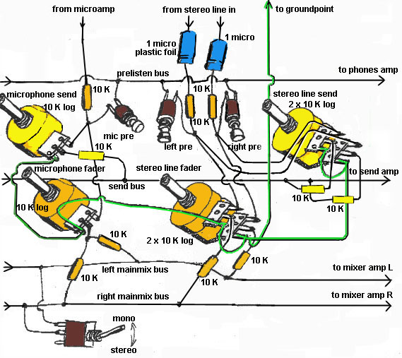
The place for pre-fader (pfl) send
potentiometers is just before main mixer faders (one more SUM amp is needed
-> for mono send submix).
The elements for
send submix are in yellow colour. If you don't need send submix you can
eliminate all the yellow elements. If you need more submix groups just replicate
same ' yellow' configurations.
Double
potentiometers are necessary because we don't use 'buffers' for the line inputs
(-> look up ).
Faders here are rotary logaritmic potentiometers (instead of 'sliders'
which are not cheap, or no good!), however better (more expensive) pots will
serve you better, double for the stereo input control, single for the mono/
microphone control.
After faders
(through equal value resistors) we connect (for the stereo inputs) all left to
the left sum common strip (bus), all right to the right sum common strip and for
the mono/ microphone to both (one resistor goes to left sum strip, one resistor
goes to right sum strip).
Prelistening can be done easiest by
pushbuttons, taking the signal from before the fader - simplest solution uses
just two-pole pushbutton (-> connected when pushed), more practical solution
needs a three-pole pushbutton (see the picture? soon!) - one pole (the middle
one in three-pole) goes to (common) prelisten line (strip, bus) and further to
the phones volume potentiometer.
For the stereo/ mono
switch of mixer output use a two-pole switch between the left sum strip and the
right sum strip.
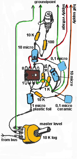
At this point we can add another double potentiometer (same as the
above ones) for the master level -> and now we come to summing amplifiers:
Summing amplifiers amplify the sums
of input signals and provide for the impedance transformation (from high to low)
- which serves best for feeding the output signal to amplifier, headphones,
computer,...
We need two/
three kinds -> for the prelisten/ phones, for the main mixer output, for the
send submix output (if needed).
Again they are
build in the exactly the same manner as the microphone preamps - except the
feedback resistor (going from pin 6 to 2) is about 10 times smaller ->
10Kohms. But for phones amplifier it should be larger -> 100Kohms. Experiment
with this (feedback) resistor!
All connections
to grounds should go separately to common ground point in stabilizer (see above)
and all the voltage supply lines should also go separately to stabilizer (and
again: blocking capacitors should be used with each op-amp).
The best would be
to think of the ground connections which go to op-amps pins 4 as voltage supply
lines - complementary to the plus voltage supply line - these two leads should
be 'twisted' together to prevent any 'hum' induction.
Grounds which go
from the potentiometers are (same as input and output grounds) - 'signal'
grounds. Acting in this manner you prevent any possibility of 'buzz' or 'hum'.
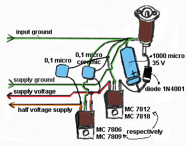
Capacitors of 10 microfarads are
electrolitic (polarized! take care!) and they should be rated for voltages above
the supply voltage -> 25V will do. Largest electrolitic capacitor is the 1000
microfarad in the voltage supply stabilizer part which should have 35 V. Just
for the case!
And the minus
pole of this capacitor should act as the common ground point for all the blocks!
We get power from
an outside 'adapter' of 12V to 24V DC secondary voltage (100mA is OK), which
lets us play safely because we don't deal with lethal tensions anymore! Just get
the right socket, connect its + socket via a forward biased diode and it will be
impossible to ruin the mixer with different adapters.
The stabilizer
circuit is the most common MC 78xx (xx = 12 or 18, which is the stabilized
output voltage). To make use of the larger dynamic range (before clipping) of
output signal - find an adapter of 18-24V DC and use MC 7818 (and MC 7809 as
you'll find in the next paragraph).
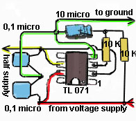
The op-amps need
a split voltage supply, so we let them float exactly in the middle of stabilized
supply voltage and ground. This is done by voltage divider resistors and a
voltage follower (again an op-amp!) or we could use another MC 78yy (yy = half
the xx) just after the first one. The second one is a better solution in some
ways but it does not adapt if for any reason a change in main stabilised supply
voltage occurs.
And that's all
(for now). In future you may expact some image files for PCBs, because the
building on the perforated board seems too much time & energy consuming.
Borut